| I am constantly
surprised and pleased by the innovative ways that Autodesk®
Architectural Desktop users manipulate the program to come up with new
and ingenious productivity tools. If you haven't looked at the Download
Center at PointA, you may be missing some unique applications of the
program. In this tutorial, you will learn how to create a parametric
truss installer using the CURTAIN WALL and STRUCTURAL MEMBERS commands.
Creating a
Custom Truss Using the CURTAIN WALL Command
1. Start a new
Autodesk Architectural Desktop 3.3 drawing using the Aec arch [imperial]
template, and select the Model layout.
2. Using the LINE
and SPLINE commands, create a truss similar to the one shown in Figure
1.
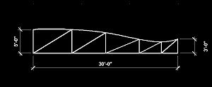
Figure 1: Create a custom truss drawing.
3. Select Design >
Curtain Walls > Convert Linework to Curtain Wall from the Main menu.
4. Select the line
work of the truss and press the Enter key.
5. Press the Enter
key again to accept the default baseline.
6. Enter Y
(yes) at the next command-line prompt, and press the Enter key to erase
the layout geometry (see Figure 2).
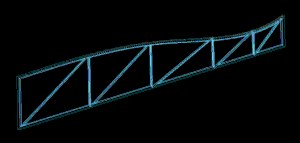
Figure 2: The custom truss.
7. Select View >
Shade > Flat Shaded from the main menu. Note that the webs are filled
in. This is because you are using a Curtain Wall object, and the webs
contain panels (see Figure 3).
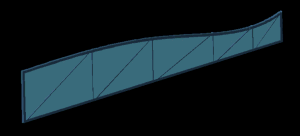
Figure 3: Flat shading the truss shows the filled in panels.
8. Select Desktop
> Style Manager from the Main menu to bring up the Style Manager dialog
box.
9. In this dialog
box double-click the Curtain Walls Styles icon to bring up all the
Curtain Wall Styles.
10. Select the New
Style icon at the top toolbar to create a new style and name it CUSTOM
TRUSS. Click OK to close the Style Manager dialog box.
11. Select the
truss, right-click, and select Curtain Wall Properties from the
contextual menu that appears to open the Curtain Wall Properties dialog
box.
12. In this dialog
box select the Style tab and choose CUSTOM TRUSS (this assigns that
style to your truss).
13. Select the
Design Rules tab.
14. On that tab,
click the Infills icon, change the Panel Thickness to 0", and click OK
(see Figure 4).
15. Save your
Truss Style.
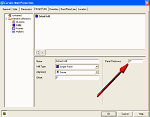
Figure 4: In the Curtain Walls Properties dialog box set Panel
Thickness to 0".
(click image to enlarge)
You now have a
truss that you can use and shade (see Figure 5).
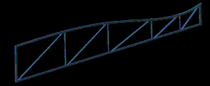
Figure 5: The shaded truss with the panels set to 0" thickness.
|
Note: I
could have modeled this truss with solid-modeling tools, but using
the Curtain Wall method, you can immediately change the properties
and profiles of truss members from the Design Rules tab of the
Curtain Wall Properties dialog box. Because of space limitations
for this article, I chose not to show those steps.
|
The Parametric
Truss Installer
Now you are going
to make a Custom Structural Member, and attach the truss to it at
designated intervals:
1. If you have
closed your file, open the file with your new truss.
2. Set the view to
Right View, and Zoom to extents.
3. Make sure the
UCS is in the Plan position with Y pointing up and X to the right.
To make this truss
installer work, you must create a Custom Structural Member Shape that
takes the place of the "truss ties" or lateral bracing.
Creating a
Custom Shape for the Structural Member
1. From the Main menu, select Draw > Rectangle and create a 3 ½"-by-1
½"-high rectangle. Copy and place two of these rectangles (future
braces) as shown in Figure 6.
|
Note: Be
sure to place the rectangles on the same elevation as the truss.
If you select the truss and right-click, you can set the truss Z
elevation to 0. When you draw the rectangles, they will then be at
the same elevation as the truss.
|
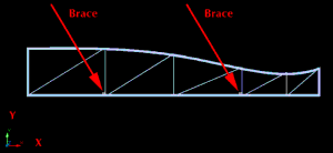
Figure 6: Be sure to place the rectangles on the same elevation as
the truss.
2. Enter -aecsmembershapedefine
at the command line and press the Enter key.
3. Enter N
(new) at the command line and press the Enter key.
4. Enter TRUSS
BRACING at the command line and press the Enter key.
5. Enter G
(graphics) at the command line and press the Enter key.
6. Enter DES
(design) at the command line and press the Enter key.
7. Enter N
(no) at the command line when you are prompted to erase the polyline,
and press the Enter key.
8. Select the left
rectangle you placed at the bottom of the truss when you are prompted to
select a closed polyline.
9. Enter Y
(yes) at the command line when prompted to add another ring and press
the Enter key.
10. Select the
other rectangles you placed at the bottom of the truss.
11. Enter N
(no) at the command line when prompted to indicate whether the ring is a
void area, and press the Enter key.
12. Enter N
(no) at the command line when prompted to add another ring and press the
Enter key.
13. Pick the
lower-left corner of the truss as the Insertion point, and press the
Enter key three times to end the command.
14. Save the new
structural member shape.
Making the
Truss into a Block
You must now reorient the UCS so that the TRUSS BRACING member will
import in the correct direction in relation to the bracing.
1. Change the
Viewport view to SW Isometric.
2. Enter UCS
at the command line and press the Enter key twice (this sets the UCS in
the World Position with Z direction up).
3. Again enter
UCS at the command line and press the Enter key
4. Enter N
(new) at the command line and press the Enter key.
5. Enter Z
at the command line and press the Enter key.
6. Enter -90
at the command line and press the Enter key.
Structural members
always extend in the X direction. Your truss is now perpendicular to the
Z direction (see Figure 7).
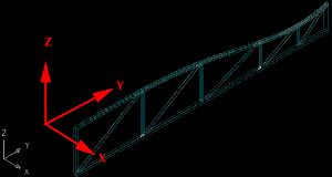
Figure 7: Structural members always extend in the X direction.
7. Select Draw >
Block > Make from the Main menu.
8. Name the block
TRUSS, select your truss and the rectangles, and pick the same
lower-left corner of the truss you picked for the custom structural
member insertion point.
9. Save your file.
You have now made
the truss into a block called TRUSS.
Creating the
AUTOTRUSS (Putting It All Together)
1. Select
Structural Members > Member Styles to open the Style Manager dialog box.
2. In this dialog
box select the New Style icon, create a new style called AUTOTRUSS, and
press the Apply button.
3. Select the
AUTOTRUSS icon, right-click, and select Edit from the contextual menu to
open the Structural Member Style Properties dialog box.
4. In this dialog
box select the Design Rules tab.
5. From the Name
drop-down list, select TRUSS BRACING (see Figure 8).
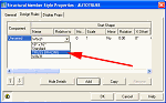
Figure 8: From the Name drop-down list, select TRUSS BRACING.
(click image to enlarge)
6. Change to the
Display Props tab.
7. Attach an
override to the Structural Member Style by selecting the Attached check
box (see Figure 9).
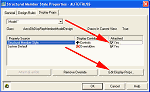
Figure 9: Attach an override to the Structural Member Style.
(click image to enlarge)
8. Click the Edit
Display Props button to open the Entity Properties dialog box.
9. In this dialog
box select the Other tab and click the Add button, which opens the
Custom Block dialog box.
10. In this dialog
box click the Select Block button, which opens the the Select A Block
dialog box.
11. Select TRUSS
(see Figure 10).
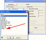
Figure 10: Select TRUSS from the Select A Block dialog box.
(click image to enlarge)
12. Click OK to
return to the Custom Block dialog box.
13. In this dialog
box select the Repeat Block Display check box, and enter 24" in
the Space Between text box (see Figure 11).
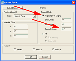
Figure 11: Enter 24" in the Space Between text box.
(click image to enlarge)
14. Click OK and
close all the dialog boxes.
Trying Out Your
New Parametric Truss Installer
1. Stay in the SW Isometric view.
2. Select Design >
Structural Members > Add Beam from the Main menu to bring up the Add
Beams dialog box.
3. In this dialog
box select AUTOTRUSS from the Style drop-down list.
4. Left-click in
the viewport and drag a beam (be sure to be in ORTHO mode). Watch the
length field as you drag.
5. Drag
approximately 10', left-click, and close the Add Beams dialog box.
You now have
multiple trusses 24" apart connected by their bracing (see Figure 12).
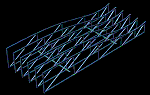
Figure 12: The Structural Member Style acting as a parametric truss
installer.
(click image to enlarge)
Conclusion
This tutorial
shows just a small example of the drawing power built in to Autodesk
Architectural Desktop 3.3. Changing the TRUSS block can now easily
modify the parametric AUTOTRUSS structural member. Because the AUTOTRUSS
structural member is parametric, changes to the TRUSS block, the bracing
shape, the spacing, and so on are automatically reflected in the
AUTOTRUSS. You can do all this after you have placed the parametric
truss installer in the building, so you can easily try out different
roof and floor configurations.
If you have
discovered new uses for Autodesk Architectural Desktop 3.3 AEC objects
and commands, please share them through the Point A AEC Download Center.
I uploaded the parametric AUTOTRUSS Structural Member Style to the Point
A Download Center for those of you who would like to use it.
Good Luck, Ed
Goldberg AIA
|
)
)
)
)
)
)