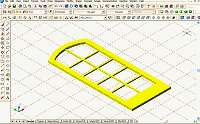
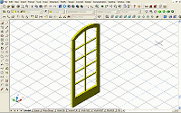
Placing the
New Door, Mullions, and Jamb into the New Door Style
1. Change to SW Isometric View.
2. Select Design >
Doors > Door Styles from the Main menu to bring up the Style Manager.
3. At the Style
Manager select the Standard door, right-click, and select Copy from the
contextual menu.
4. Right-click
again and select Paste from the contextual menu.
5. Rename
(Standard 2) to French door Single and click the OK button.
6. Place a
10'-high standard wall approximately 12' long in your drawing.
7. Select the
wall, right-click, and select Insert > Door from the contextual menu to
bring up the Add Doors dialog box.
8. At the Add
Doors dialog box, select the French door Single from the Style drop down
list, and set the size to 3'-0" X 6'-8".
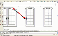
9. Place the
French door Single Style 3'-0" X 6'-8" door in the wall (see Figure 12).
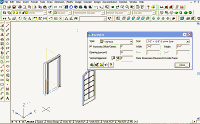
Figure 12: Place a door in a wall.
(click image to enlarge)
10. Select Draw >
Block > Make from the Main menu to bring up the Block Definition dialog
box.
11. In this dialog
box create the name French Door and Mullions.
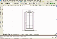
12. Select the
door and mullions that you created and pick an insertion point at the
bottom left of the door (see Figure 13).
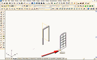
Figure 13: Block the new solid door.
(click image to enlarge)
You have now
created a block of the door.
13. Select the
door in the wall, right-click and select Edit Door Style from the
contextual menu to bring up the Door Style Properties dialog box.
14. In this dialog
box, select the Display Props tab.
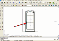
15. Attach an
override to the Door Style by selecting the first check box under the
Attached column (see Figure 14).
16. Make sure
Model is selected on the Display Props tab.
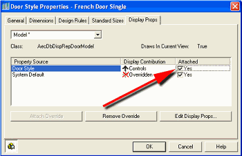
Figure 14: Attach an override to the Door Style.
17. Click the Edit
Display Props button to bring up the Entity Properties dialog box.
18. In this dialog
box, select the Other tab.
19. Click the Add
button to bring up the Custom Block dialog box (see Figure 15).
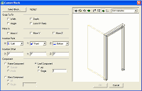
Figure 15: Bring up the Custom Block dialog box.
(click image to enlarge)
20. In this dialog
box, click the Select Block button to bring up the Select A Block dialog
box (see Figure 16).
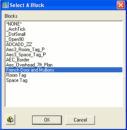
Figure 16: Bring up the Select A Block dialog box.
21. In this dialog
box select the door block you made (French Door and Mullions), and click
the OK button, which returns you to the Custom Block dialog box.
You have now added
the door to French Door style.
22. In the Custom
Block dialog box, select the Leaf Component and All radio buttons, set
the Y Insertion Point to Back (see Figure 17), and click the OK button
to return to the Entity Properties dialog box.
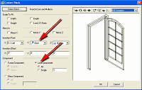
Figure 17: Set the Y Insertion Point to Back.
(click image to enlarge)
23. In this dialog
box select the Layer/Color/Linetype tab.
24. Clear the Door
Panel and Swing Visible icons (see Figure 18). Note that French Door and
Mullions now appears as a component.
25. Click the OK
button to finish and return to the drawing screen (see Figure 18).
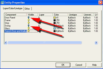
Figure 18: Clear the Door Panel and Swing Visible icons.
To create the
jamb:
26. Select the
door in the wall, right-click, and select Edit Door Style from the
contextual menu. The Door Style Properties dialog box for the French
Door Single component displays.
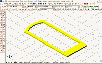
27. Select the
Design Rules tab (if it is not already current), select the Custom radio
button, and from the drop-down list that appears select French Jamb (see
Figure 19).
28. Click the OK
button to close this dialog box and return to your drawing (see Figure
19).
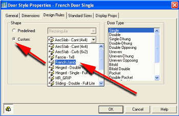
Figure 19: Select the custom jamb.
29. Save this
file. You may want to reuse it.
You are done! You
now have a new custom door style to use and share. Take the door for a
test-drive by placing several with different setting Openings (percent)
(see Figure 20).
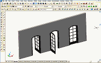
Figure 20: Customized door placed in sample wall.
(click image to enlarge)
Conclusion
You can apply the techniques we've been working with in this tutorial to
windows, curtain walls, and window assemblies. Styles are an important
part of the productivity benefits of using Autodesk Architectural
Desktop 3.3. Once mastered, the creation of customized Styles will allow
you to quickly and easily add new content to your drawings.
Don't forget to go
to the Point A
Download Center, where you'll find a variety of customized doors and
windows. Check them out. And if you create some new Styles, share them.
Good Luck, Ed
Goldberg.
|
