|
Last
month I discussed stairs and stair enclosures. But what is a
stair without a railing? According to the 1990 BOCA building
code, "Handrails are required for all stairways except for
stairways with less than three risers serving a single dwelling
unit or which are not in an exit access corridor or aisle, exit,
or exit discharge." Clearly, you're going to be designing a
lot of railings. So why not use Autodesk® Architectural Desktop
3.0/ 3.3's intelligent AEC Railing Objects and save yourself
some time and effort?
In this
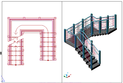
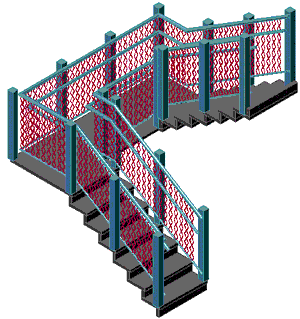
tutorial, you will learn how to modify a railing. Several years
ago, I designed an intertwined steel-mesh stair for a university
building, and we'll use that design as the basis for this
tutorial.
The
Mesh Shape
1. Start a new drawing using the Aec arch [imperial] template,
and select the Model Layout.
2. Select
the Line icon from the Draw toolbar and draw the shape shown in
Figure 1.
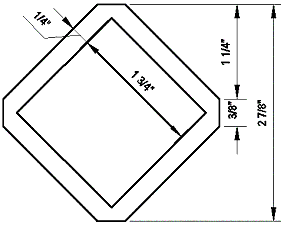
Figure 1: Draw this shape for the intertwined steel mesh.
3. Using
Modify > Object > Polyline from the Main toolbar, change
the inner 1 ¾" square into a polyline.
4. Using
Modify > Object > Polyline from the Main toolbar, change
the outer shape into a polyline.
5. Select
Draw > Region from the Main toolbar and select the two shapes
to make them Regions.
6. Select
Modify > Solids Editing > Subtract from the Main toolbar
and subtract the inner Region from the outer Region.
7. Select
the Array icon from the Modify toolbar, and array the Region 7
rows as shown in Figure 2. (Select Flat Shaded from the Shade
toolbar to display the region with shading.)

Figure 2: Array the regions to create a new shape.
You have
now created the mesh shape.
3D
Rotating and Creating a Block
1. Select the SW Isometric View icon from the View toolbar to
change the view.
2. Select
Modify > 3D Operation > Rotate 3D from the Main toolbar.
3. Select
all seven shapes, and press the Spacebar.
4. Enter X
in the command line to rotate around the X-axis, and press the
Spacebar.
5. Select
the point shown in Figure 3 when requested to "specify a
point on the X axis <0,0,0>" on the Command line.
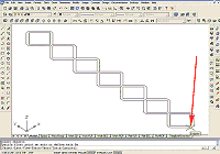
Figure 3: Use the ROTATE 3D command to rotate the shape.
(click image to enlarge)
6. Enter 90
on the Command line for the Specified rotation angle, and press
the Spacebar.
7. Perform
a Zoom Extents (see Figure 4). You have now created the mesh and
placed it in the Z direction.
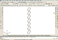
Figure 4: After rotation, the shape is ready to be made into
a Block.
(click image to enlarge)
8. Select
Draw > Block > Make... from the Main toolbar to bring up
the Block Definition dialog box.
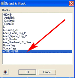
9. Name
the new block WIRE MESH.
10. Click
the Base Point-Pick point button, and select the same point on
the wire mesh object as in Step 5.
11. When
the Block Definition dialog box returns, click the Select
objects button, and select the entire wire mesh object.
12. When
the Block Definition dialog box returns, select the Delete radio
button, and then click OK to close the dialog box.
Your have
now created the WIRE MESH block, and the drawing editor should
be clear.
|


