Modifying
Interior Space Plans
by: Ed Goldberg
URL: http://localhost/gotoPointA.jsp?dest=2_6gold_hl
|
In last month's tutorial, Interior Space Planning Using Space Objects and Boundaries we used Autodesk® Architectural Desktop 3 to make an interior space plan using Space Objects and Space boundaries. This month we take that exercise several steps forward, adding a hallway and doors to the plan. Using the interactive Section Object, we can easily analyze our project in section as we modify it in plan. To begin, you'll have to open last month's exercise. Creating
the Hallway Space Object 2. Activate the Spaces toolbar, and place it in a convenient spot in the drawing area.
3. Click the Work-FLR Layout tab, and set the viewport to Top View (see Figure 2). Click OK to return to the drawing.
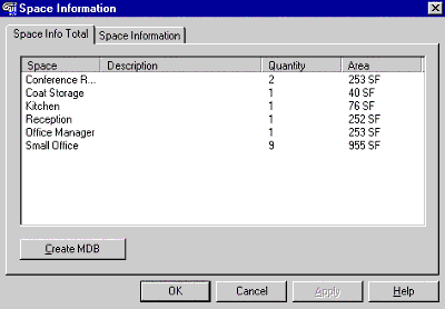
If you want to determine how much space remains for the hallway, it's easy. 4. Click the Space Inquiry icon on the Spaces toolbar. The Space Information dialog box displays. Select the Space Info Total tab (see Figure 3). Add up the numbers in the Area column and subtract that number from the total square footage for this project. Click OK to return to the drawing.
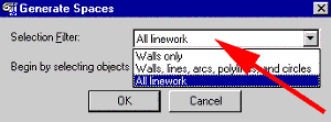
5. Click the Generate Spaces icon on the Spaces toolbar. The Generate Spaces dialog box displays (see Figure 4). 6. From the Selection Filter drop-down list, select the All Linework option and click OK.
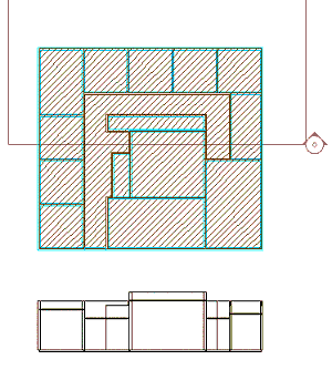
7. Select all the spaces and boundaries with a window selection and the area in which the hallway is to be added, and press Enter. 8. At the command line, select an internal point in the hallway area, and press Enter. The hallway area now fills in as a new Space Object. 9. Select the new Space Object and right-click to bring up the context-sensitive menu. 10. Select the Edit Space Style option from this menu, which brings up the Space Style Properties dialog box. 11. Select the General tab, name the Space HALLWAY (see Figure 5), and click OK.
12. Again, select the Space Object, now called HALLWAY. Right-click to bring up the context-sensitive menu. 13. Select the Space Properties option from the menu, which opens the Space Properties dialog box. 14. Select the Dimensions tab, and change the Space Height to 7'-0". The floor-to-ceiling height becomes 7' 0" (see Figure 6).
15. Close off the HALLWAY Space Object by selecting Concept > Space Boundaries > Add Boundary, and placing a new boundary at the hallway entrance.
|
)
)
)
)
)
)
|
Now let's look at the space plan in section view. Here's how. 16. Activate the Utilities toolbar, and place it in a convenient spot in the drawing area. 17. Working in the Top View, select the Documentation > Documentation Content > Section Marks, which brings up the Design Center dialog box. Left-click, hold, and drag Section Mark A1 into your drawing. 18. Release the mouse button, reclick, and drag the section mark horizontally across your plan. 19. Click again to end the section line, and press the Enter key. The Edit Attributes dialog box appears. Accept the default Section Mark number by clicking OK. (Normally you would enter the number or letter you've used to coordinate with your other drawings.) 20. At the command-line request, Specify side for arrow, drag the section arrow vertically, and click your mouse button to go to the next command-line request. 21. When asked, Add AEC section object?, press Enter to indicate yes, which also returns you to the drawing. You have now placed a Section Object (see Figure 8). There are other ways to do this, but this method is probably the simplest and easiest.
22. Select the Section Object, and right-click to bring up the context-sensitive menu. 23. Select the Generate Section option from this menu, which opens the Generate Section/Elevation dialog box. 24. Select the 2D/ Elevation Object with Hidden Line Removal radio button, then select the Pick Point button and pick a point in your drawing below your space plan. 25. When the Generate Section/Elevation dialog box returns, select the Select Objects button and select all your spaces and boundaries with a window selection, and press the Enter key. When the Generate Section/Elevation dialog box returns again, click OK to complete the command. A detail section now appears below your space plan. Modify the plan, and the section will change (see Figure 9).
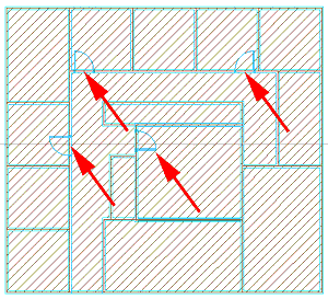
26. Select any point on the Space boundary, and right-click to bring up the context- sensitive menu. 27. Select the Insert option, then the Door option, which opens the Add Doors dialog box. 28. Place 3' wide doors as shown in Figure 10. Click OK when you're finished. 29. Select the detail section you placed below your floor plan, and right-click to bring up the context-sensitive menu. 30. Select the Update option from the menu, which opens the Generate Section/Elevation dialog box. When this dialog box appears, click OK to close the command. The section automatically updates. Now the doors appear in the section. Note the doors and doorjambs shown in the Before and After graphics. Try changing ceiling heights and floors; add doors and windows. Every time you make a change in the plan, and update your section view, the section view changes to reflect the plan changes. As you move forward in the design process you will retain these sections to XREF into your construction documents. Conclusion |
)
H. Edward Goldberg, AIA, is a practicing architect and industrial designer, as well as Coordinator of Industrial Design at Towson University in Towson, Maryland. Ed can be reached at h.e.goldberg@verizon.net.