|
I get more
questions about the Autodesk® Architectural Desktop
implementation of curtain walls than on any other topic. Curtain
walls as a modern building concept came into the architectural
lexicon with the invention of steel frame and concrete frame
buildings at the end of the 19th century.
Autodesk
Architectural Desktop 3.3 has a complete Curtain Wall system.
Besides the curtain wall itself, Curtain Wall objects are used as
a framework or grid for the insertion of windows, doors, and
window assemblies. As with many Architectural Desktop 3.3
features, users have found many uses for Curtain Wall objects
other than those originally intended by the software developers.
If you go to the free Download Center in the AEC section of Point
A, you will find these objects used in several new ways. For
example, one new Curtain Wall style is used to represent a CMU
block wall, it even includes mortar joints, and another style is
used to represent a railing.
In this
tutorial, you will learn how to create a Curtain Wall object and
set the object's Style properties.
Creating
a Curtain Wall Object from a Layout Grid
1. Start a new drawing using the Aec arch [imperial] template, and
select the Model Layout.
2. Select
Desktop > Layout Tools > Add Layout Grid (2D) from the main
menu to bring up the Add Layout Grid dialog box.
3. In this
dialog box, set the following:
- Shape =
Rectangular
- X-Width =
40'
- Y-Depth =
20'
4. Place the
grid in the model layout as shown in Figure 1.
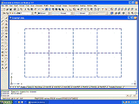
Figure 1: Place a 2D layout grid in the model layout.
(click image to enlarge)
5. Select
Design > Curtain Walls > Convert Layout Grid to Curtain Wall
from the main menu (see Figure 2).
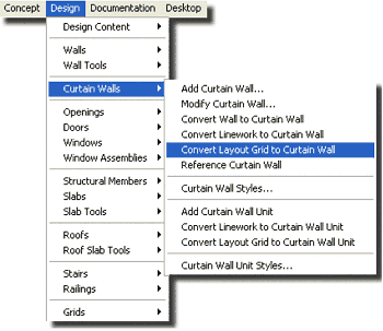
Figure 2: Convert the layout grid to a Curtain Wall object.
6. Select
the 2D layout grid you placed in Step 4, and enter Y (for Yes)
in the command line and press the Enter key.
7. Enter V
(for vertical) on the command line and press the Enter key
to bring up the Curtain Wall Style Name dialog box.
8. In this
dialog box enter the name TEST CURTAIN WALL, and click OK.
The layout
grid disappears, and the new curtain wall appears in the Plan
View.
9. Place the
curtain wall in an SW Isometric View by clicking the SW Isometric
View icon in the View toolbar(see Figure 3).
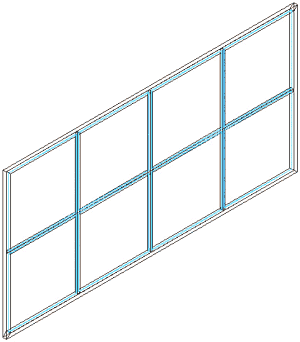
Figure 3: The Curtain Wall object matches the layout grid, and
the primary grid is vertical.
Setting
Curtain Wall Style Properties
To set properties for a curtain wall style:
1.
Right-click the curtain wall you just created, and select Edit
Curtain Wall Style from the context menu to bring up the Curtain
Wall Style Properties dialog box.
2. In this
dialog box, select the Design Rules tab.
3. Click the
Floating Viewer icon to bring up the viewer. Adjust the dialog box
and viewer so you can see both of them at the same time (see
Figure 4).
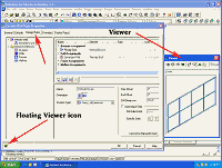
Figure 4: Place the Viewer screen next to the Curtain Wall
Style Properties dialog box.
(click image to enlarge)
Notice that
the Primary Grid Element drop-down list is set to Vertical
Division, the Orientation icon is shown as vertical, and the Cell
Dimension is set to 10'-0" (see Figure 5).
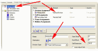
Figure 5: The Primary Grid Cell Dimension is 10'-0".
(click image to enlarge)
Watch the
changes to the curtain wall in the viewer as you change the Design
Rules.
4. Click the
New Cell Assignment icon to create a new cell assignment.
5. From the
Cell Location Assignment drop-down menu, select the Start and End
check boxes (see Figure 6).

Figure 6: Click the New Cell Assignment icon to create a new
cell assignment.
(click image to enlarge)
Notice the
change in the curtain wall (see Figure 7).
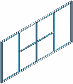
Figure 7: The Curtain Wall object now has a new cell
assignment.
|