Walls
101 with Autodesk Architectural Desktop 3
by: Ed Goldberg
URL: http://localhost/gotoPointA.jsp?dest=2_7gold_hl
|
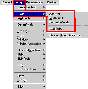
Creating walls and their components is fundamental to all architectural projects. Autodesk® Architectural Desktop 3 offers a complete set of intelligent design objects—intelligent objects know their form and function and how they relate to other drawing objects—and tools that make modifying them a quick and easy task. The following tutorial will help you better understand how to use some of these tools and commands. Located under Design on the software's main menu, the Wall drop-down menu contains the commands you'll use to make and modify any type of wall (see Figure 1).
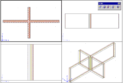
For this tutorial you will need four Paperspace viewports in the Work-3D Layout.
Creating
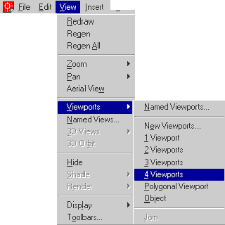
the four Paperspace viewports 2. At the command line, accept the default <Fit> by pressing Enter or the Spacebar. <Fit> expands the viewports fill the entire printable sheet.
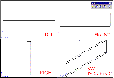
3. Activate the View toolbar and place it in a convenient place on the screen. 4. Set the Viewports to the following views starting at the top left and moving clockwise: Top View, Front View, SW Isometric View, and Right View. Save your drawing as Wall_tutorial. Creating
Walls
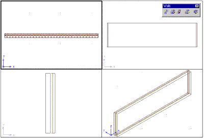
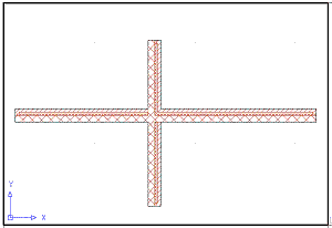
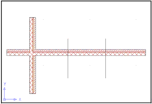
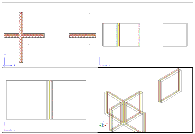
2. Select the Add Wall icon to bring up the Add Walls dialog box. 3. In this dialog box, leave the Style as Standard, change the Width to 12", and change the Justify to Left, which causes the wall to be drawn to the right side of the cursor as you move from left to right. 4. Click the ORTHO button , then click in the Top View viewport, drag the cursor to the right, and enter 30' in the command line. Press the Spacebar or Enter key twice to complete the command. Now perform a Zoom Extents in each viewport (see Figure 4).
You have just created your first wall. |
H. Edward Goldberg, AIA, is a practicing architect and industrial designer, as well as Coordinator of Industrial Design at Towson University in Towson, Maryland. Ed can be reached at h.e.goldberg@verizon.net.
