by: Ed Goldberg
URL: http://localhost/gotoPointA.jsp?dest=2_9gold_hl
|
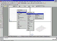
Construction documents would be easy to create if walls were simple, straight forms—but they usually are not. Both Autodesk® Architectural Desktop 3 and 3.3 have the tools you need to create unusual walls quickly and easily. The wall modification tools such as Wall Modifiers, Sweep Profiles, and so on are located in the Wall Tools submenu under the Design main menu. As with all the Architectural Desktop 3 and 3.3 menus, the Wall Tools menu can be reached by right-clicking in any viewport and following down the menu tree (be sure no object has been selected). For these tutorials, we will again use the four-view drawing template (Walls_Tutorial) we created two months ago in Walls 101 with Autodesk Architectural Desktop 3. If you do not have Walls_Tutorial template, please download the template from here (91 KB). Wall Modifiers Wall Modifiers are used to add objects such as pilasters to the wall. Creating
the Wall 2. Change to the Work_3D layout tab; activate the top-left viewport (Top View). 3. Right-click to bring up the contextual menu, select Design > Walls > Add Wall from the menu (see Figure 1).
4. At the Add Walls dialog box, add a 30' long Stud-4 Rigid-1.5 Air-1 Brick 4 wall. (Place the wall starting from left to right.) 5. Select the wall, right-click, select Plan Tools > Reverse. (This will reverse where the wall starts and the side on which brick exists.) 6. Zoom extents in all viewports. Adding
the Wall Modifier
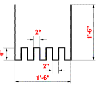
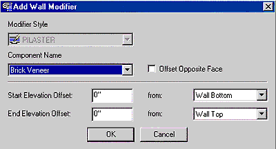
2. Right-click in the top-left viewport (Top View) and select Design > Wall Tools > Convert Polyline to Wall Modifier from the contextual menu that appears. 3. Select the wall when requested at the command line, and then select the polyline you created. 4. Enter Y at the command line, and press Enter to bring up the New Wall Modifier Style Name dialog box. 5. In this dialog box, enter PILASTER, and click OK to bring up the Add Wall Modifier dialog box. 6. In this dialog box, select Brick Veneer from the Component Name drop-down list, and click OK (see Figure 4).
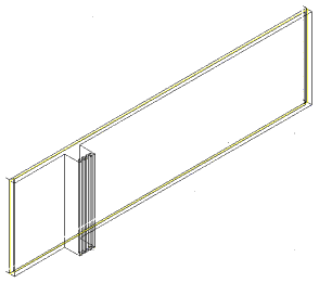
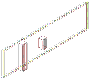
You have now created a Wall Modifier called PILASTER and made it part of the wall. Because you chose the brick component of the wall, the pilaster will be brick (see Figure 5).
Modifying
the Wall Modifier 2. Select the Wall Modifiers tab in this dialog box.
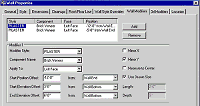
3. Click Add (to the right of the first pane of this dialog box) to add a Standard-style Wall Modifier. (The phrase Modifier 2 will now appear in the Modifier pane just below the first pane.) 4. Under Modifier 2, change the following (see Figure 6):
5. Click OK to create the second pilaster (see Figure 7).
Experiment with the settings in the Wall Modifiers tab, and add more modifiers. Use the Style Manager to purge Wall Modifiers. |
|
Sweep Profiles Use Sweep Profiles to create walls with unusual profiles such as slanted walls. Here's how:
This returns the wall to its original state and reverses its direction. Creating
a Profile
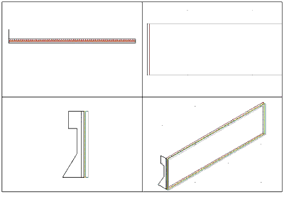
2. Right-click and select Desktop > Profiles > Profile definitions from the contextual menu to bring up the Style Manager dialog box. 3. In this dialog box, select the New Style icon from the top toolbar, and create a new style called SLOPED WALL. 4. With the SLOPED WALL style selected, select the Set From icon from the top toolbar and select the closed polyline you created. 5. Enter N at the command line when asked to Add Another Ring, and press the Enter key. 6. At the next Command prompt, select the lower-right corner of the closed polyline. When the Style Manager dialog box reappears, click OK. You have now created a profile called SLOPED WALL. Adding
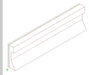
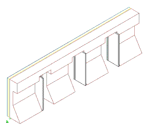
the Sweep Profile 2. Right-click in any viewport and select Design > Wall Tools > Sweep Profile from the contextual menu. 3. At the command prompt, select the wall and press the Enter key to bring up the Profile Definitions dialog box. 4. In this dialog box select the SLOPED WALL definition and click OK. 5. Press the F2 key (function key) to bring up the Text window. The Text window displays the components of the wall you selected. 6. Enter 1 (Brick Veneer), and press the Enter key to close the Text window. The wall is now the shape of the profile (see Figure 9).
7. Select the wall, right-click, and select Insert > Door from the contextual menu. 8. Insert three doors in the wall. The wall is automatically configured to accept the doors (see Figure 10). You can adjust this wall component by going to the Wall Properties dialog box and opening the 3d Modifiers tab, where you will find Wall Sweep Modifiers. Conclusion Wall Modifiers and Sweep Profiles are just of a few of the new tools that aid in creating wall geometry; the above lessons only address a small portion of the total feature set. Utilizing polyline profiles, you can create practically any wall shape and modifier; experiment with different ones to create specialized walls and elements. |
H. Edward Goldberg, AIA, is a practicing architect and industrial designer, as well as Coordinator of Industrial Design at Towson University in Towson, Maryland. Ed can be reached at h.e.goldberg@verizon.net.
