by: Ed Goldberg
URL: http://pointa.autodesk.com/gotoPointA.jsp?dest=15756
|
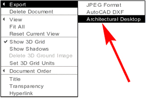
Autodesk® Architectural Studio software is a new program developed as an easy-to-learn design tool. Think of it as an architect's or designer's desk. With Autodesk Architectural Studio you can work in both 2D and 3D as well as import animations and digital pictures. The program has an excellent export capability with which you can send your 3D designs directly to Autodesk® Architectural Desktop 3.3 as mass elements. You can also export the 2D and 3D designs as DXF files (Autodesk's web-ready drawing file format) to any program that reads this format. In this
tutorial, you will learn some basics of Autodesk Architectural
Studio, and how it integrates with Autodesk Architectural Desktop
3.3.
Creating
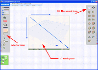
a Design in Autodesk Architectural Studio 1. Start a new workspace. 2. Using the pointer tool, select the 3D Document icon from the 3D toolbar on the right, and drag a 3D drawing space (see Figure 1).
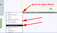
3. Using the pointer tool, click the triangle at the lower left of the 3D workspace and select Show 3D Grid and Set 3D Grid Units from the drop-down menu (see Figure 2).
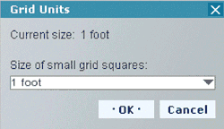
4. When the Grid Units dialog box appears, set it to 1-foot units, and click OK (see Figure 3).
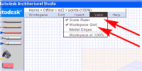
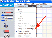
5. Finally, select View from the main menu and then select Scale Ruler, and Workspace Grid. Select Edit from the main menu and then select Snap to Geometry and Snap to Grid (see Figures 4 and 5).
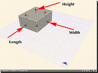
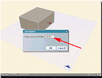
6. Select the Rectangular Solid icon from the 3D toolbar on the right, and drag on the 3D grid to create a rectangular solid. 7. Using the Selector icon from the 2D toolbar on the left, select the solid to bring up its control points (see Figure 6). 8. Right-click the Width point to open the Get Input dialog box (see Figure 7).
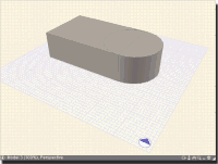
9. Input 30 in the Enter value for Width text box and press the Enter key. Repeat until you have a unit 20x30x10 high. (You do not need to put in feet or inch signs; you are in foot units.) 10. Click the OK button when you are finished. 11. Select the Cylinder icon from the Massing tools on the right side toolbar and drag it into the workspace so it resembles Figure 8.
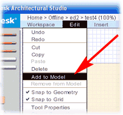
12. Holding down the Shift key, select both solid objects. 13. Select Edit > Add to Model from the main menu (see Figure 9).
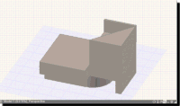
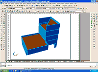
You have now joined two solids into one composite solid. 14. Continue to add solids until you have a form 50' high, similar to that shown in Figure 10. 15. Using the process described in Steps 12 and 13, create your final massing study.
|
