To print: Click here or Select File and then Print from your browser's menu
Architectural Desktop: Intelligent Railing Objects
by: Ed Goldberg
URL: http://pointa.autodesk.com/gotoPointA.jsp?dest=3_4gold

Last month I discussed stairs and stair enclosures. But what is a stair without a railing? According to the 1990 BOCA building code, "Handrails are required for all stairways except for stairways with less than three risers serving a single dwelling unit or which are not in an exit access corridor or aisle, exit, or exit discharge." Clearly, you're going to be designing a lot of railings. So why not use Autodesk® Architectural Desktop 3.0/ 3.3's intelligent AEC Railing Objects and save yourself some time and effort?

In this tutorial, you will learn how to modify a railing. Several years ago, I designed an intertwined steel-mesh stair for a university building, and we'll use that design as the basis for this tutorial.

The Mesh Shape
1. Start a new drawing using the Aec arch [imperial] template, and select the Model Layout.

2. Select the Line icon from the Draw toolbar and draw the shape shown in Figure 1.
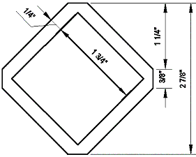

Figure 1: Draw this shape for the intertwined steel mesh.

3. Using Modify > Object > Polyline from the Main toolbar, change the inner 1 ¾" square into a polyline.

4. Using Modify > Object > Polyline from the Main toolbar, change the outer shape into a polyline.

5. Select Draw > Region from the Main toolbar and select the two shapes to make them Regions.

6. Select Modify > Solids Editing > Subtract from the Main toolbar and subtract the inner Region from the outer Region.

7. Select the Array icon from the Modify toolbar, and array the Region 7 rows as shown in Figure 2. (Select Flat Shaded from the Shade toolbar to display the region with shading.)


Figure 2: Array the regions to create a new shape.

You have now created the mesh shape.

3D Rotating and Creating a Block
1. Select the SW Isometric View icon from the View toolbar to change the view.

2. Select Modify > 3D Operation > Rotate 3D from the Main toolbar.

3. Select all seven shapes, and press the Spacebar.

4. Enter X in the command line to rotate around the X-axis, and press the Spacebar.

5. Select the point shown in Figure 3 when requested to "specify a point on the X axis <0,0,0>" on the Command line.
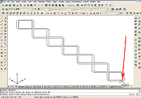

Figure 3: Use the ROTATE 3D command to rotate the shape.
(click image to enlarge)

6. Enter 90 on the Command line for the Specified rotation angle, and press the Spacebar.

7. Perform a Zoom Extents (see Figure 4). You have now created the mesh and placed it in the Z direction.
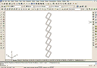

Figure 4: After rotation, the shape is ready to be made into a Block.
(click image to enlarge)

8. Select Draw > Block > Make... from the Main toolbar to bring up the Block Definition dialog box.

9. Name the new block WIRE MESH.

10. Click the Base Point-Pick point button, and select the same point on the wire mesh object as in Step 5.

11. When the Block Definition dialog box returns, click the Select objects button, and select the entire wire mesh object.

12. When the Block Definition dialog box returns, select the Delete radio button, and then click OK to close the dialog box.

Your have now created the WIRE MESH block, and the drawing editor should be clear.


Creating the Wire Mesh Railing Style
1. Open the Stairs–Railings toolbar and place it in a convenient place.

2. Select the Railing Styles icon from that toolbar to bring up the Style Manager dialog box.

3. At the Style Manager dialog box, click the New Style icon on the Style Manager toolbar.

4. Rename the New Style to Wire Mesh Railing.

5. Double-click on the icon to the left of the words Wire Mesh Railing to bring up the Railing Styles–Wire mesh Railing dialog box.

6. Select the Display Props tab in this dialog box.

7. On that tab, set the Class drop-down list to Model.

This will allow you to edit the Display Props for the model view.

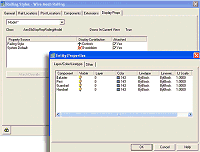
8. Attach an Override to the Railing Style by selecting the Attached check box.

9. Click the Edit Display Props... button to bring up the Entity Properties dialog box (see Figure 5).


Figure 5: Attach an Override to modify the Entity Properties of the railing.
(click image to enlarge)

10. Select the Other tab in this dialog box.

11. On that tab, click the Add... button to bring up the Custom Block dialog box.

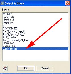
12. In this dialog box, click the Select Block... button to bring up the Select A Block dialog box.

13. In this dialog box, select WIRE MESH, and click OK to return to the Custom Block dialog box (see Figure 6).


Figure 6: Select the Block you made to use on the railing.

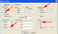
14. Again, at the Custom Block dialog box, select the Height check box under Scale to Fit. Set Insertion Point Z to Bottom. Select the Baluster check box under Component. Select the All radio button under Attach to (see Figure 7).


Figure 7: At the Custom Block dialog box, choose settings to locate the Block on the railing.
(click image to enlarge)

15. Click OK to return to the Entity Properties dialog box.

16. In this dialog box, select the Layer/Color/Linetype tab.

17. Turn off the lightbulb under visible for Baluster.

18. Click the OK buttons to close all the dialog boxes.

You have now created a new Railing style called Wire Mesh Railing. Save the Drawing as WireMesh Railing.


Using and Modifying the Wire Mesh Railing
1. Clear the WireMesh Railing drawing.

2. Change to the Work-3D layout.

3. Activate Model space.

4. Select the Add Stair icon from the Stairs–Railings toolbar to bring up the Add Stairs dialog box.

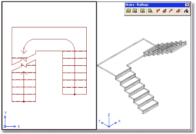
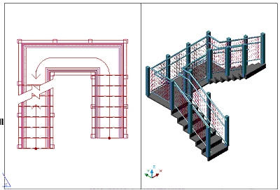
5. Select a Standard Style, U-shaped, ½ Landing, 3'-0" wide, 8' height stair, and place the stair in the Top View–Zoom Extents all both views (see Figure 8).


Figure 8: Place an AEC stair object in the Top View of your Work-3D layout.

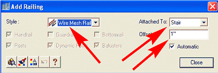
6. Select the Add Railing icon from the Stairs–Railings toolbar to bring up the Add Railing dialog box.

7. In this dialog box, select the Wire Mesh Railing Style, select Stair for Attached to, and set the offset to 1" (see Figure 9).


Figure 9: At the Add Railing dialog box, select the Wire Mesh Railing Style.

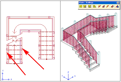
8. Select the outside and inside edges of the stair in the Top View to attach the railing (see Figure 10).


Figure 10: Select the outside and inside edges of the stair to attach the railing.

Notice that the wire mesh reaches to the surface of the stair, that there is no top or bottom rail, and that the posts are not always at the corners. To fix this:

1. Select the railing, right-click, and select Edit Railing Style from the contextual menu to bring up the Railing Styles–Wire mesh Railing dialog box.

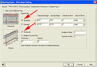
2. In this dialog box, select the Rail Locations tab.

3. On that tab, select the Guardrail and Bottomrail check boxes (see Figure 11).


Figure 11: Select the Guardrail and Bottomrail check boxes.
(click image to enlarge)

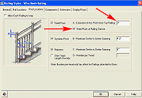
4. Select the Post Locations tab.

5. On that tab, select the Fixed Posts at Railing Corners check box, and set the Extension of ALL Posts from Top Railing field to 3" (see Figure 12).


Figure 12: Set the Extension of ALL Posts from Top Railing field to 3".
(click image to enlarge)

6. Click OK to close the dialog box.

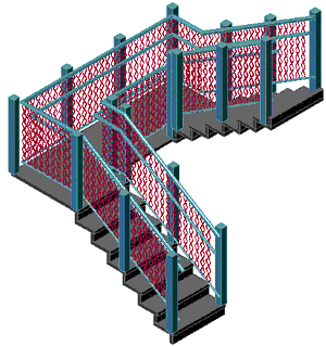
Now check your stair. Everything is correct. Shade the 3D view (see Figure 13). Save this Stair Railing Style to use in other projects (see Figure 14).


Figure 13: Shade your stair to determine if the layout is correct.


Figure 14: You can easily save and import Stair Railing Styles into other projects.

I chose to use Regions instead of solid 3D meshes for the Wire Mesh block because Regions have fewer faces and render more quickly with less computer resources. With a little practice, you will find that you can create almost any type custom railing. I posted this railing style on Point A's Download Center. It is a good idea to check out this area for free Autodesk Architectural Desktop Styles.

Good Luck, EG.


H. Edward Goldberg, AIA, is a practicing architect and industrial designer, as well as Coordinator of Industrial Design at Towson University in Towson, Maryland. Ed can be reached at h.e.goldberg@verizon.net.