|
Given
coding requirements and the fact that the rules change from
region to region, the design and detailing of stairs has always
been one of the more difficult tasks for architects and
designers. Toss in the many different types of stair
construction, and you've added even more time to the task.
Autodesk® Architectural Desktop 3.3, with its intelligent AEC
Stair and Railing objects, now makes stair design easier,
quicker, and less prone to error.
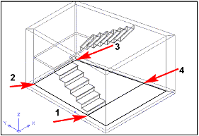
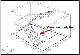
In this
tutorial, we'll use these intelligent objects to design a stair
enclosure, with stair, slab, and landing, and create its section
automatically.
|
Note:
To be comprehensive this tutorial covers the creation
of custom Profiles and Slab Edge Styles, but normally,
you will have already created a library of these
items, making for an even faster design.
|
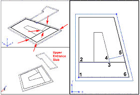
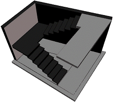
The
Stair Enclosure
1. Start a new drawing using the Aec arch [imperial] template,
and select the Work-3D Layout.
2. Change
to model space by selecting the MODEL or PAPER button at the
bottom of the screen (below the command line). If the button
reads PAPER, you are in paper space.
3. Select
the Line icon from the Draw toolbar and draw the shape shown in
Figure 1.
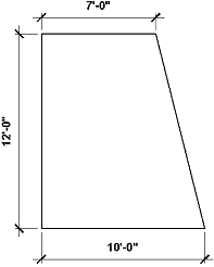
Figure 1: Draw this figure using the Line command.
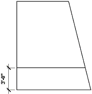
Figure 2: Offset the bottom line 3'-0" as a basis for
the landing.
4. Select
the Offset icon from the Modify toolbar and offset the bottom
line 3'-0" (see Figure 2), which we'll use later for making
a landing.
5. Select
the Convert to Walls icon from the Walls toolbar, and select the
outer lines of the enclosure.
6. Enter N
at the command line to leave (not erase) layout geometry. Press
the Enter key, which brings up the Wall Properties dialog box.
7. In this
dialog box select the Style tab.
8. On this
tab, select the CMU-8 wall style and then select the Dimensions
tab.
9. On that
tab change the Justify drop-down list to Right (this assumes
that you have drawn the walls in a clockwise direction) and
click OK to close the command.
You have
now created the wall enclosure for your stairway (see Figure 3).
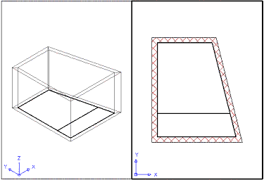
Figure 3: Use the Convert Walls icon to automatically convert
lines to walls.
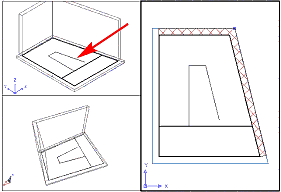
1. Select
the Convert to Slab icon from the Slabs toolbar, select all the
walls, and press the Enter key.
2. Enter N
at the command line to leave (not erase) layout geometry, and
press the Enter key.
3. At the
command line enter T for Top and press the Enter key.
4. At the
command line enter L for Left and press the Enter key.
5. At the
command line accept the default (Left or Right—it doesn't
matter) and press the Enter key, which brings up the Slab
Properties dialog box.
6. At the
Slab Properties dialog box select the Style tab and choose the
Standard style.
7. Select
the Dimensions tab, change the A-Thickness to 5", and click
OK.
You have
now created the floor slab for your stairway, but it is at the
top of your wall. To remedy that:
8. Select
the floor slab, right-click, and select Slab Properties from the
contextual menu that appears to bring up the Slab Properties
dialog box.
9. In this
dialog box select the Location tab.
10. Set
the Insertion Point Z: to -5".
11. Click
OK.
You have
now moved the 5"-thick floor slab to the base of the stair
enclosure.
(If you
had drawn the enclosure as a polyline initially, you could have
converted that to a slab and wouldn't have needed to move it
later.) For the meantime, try the first method, to practice
making and modifying slabs from walls.
|
)
)
)