To print: Click here or Select File and then Print from your browser's menu
Interior Space Planning Using Space Objects and Boundaries
by: Ed Goldberg
URL: http://localhost/gotoPointA.jsp?dest=2_5gold

Now that we've explored Autodesk® Architectural Desktop software's mass-modeling capabilities in Mass Modeling the Architectural Desktop Way and more complex concepts in Making the Most of the MASSELEMENT > CONVERT Command, we're ready to look at another design method, Space Objects and Space Boundaries.

Use this method to organize spaces and functions according to a design program or written plan that you and the client have developed. The concept of Space Objects in Release 3 hasn't changed; it still represents a three-dimensional area. Think of it as a room with ceilings, floors, walls, and so on. The Space Boundaries feature hasn't changed either: think of Space Boundaries as helping you define the walls and ceiling in this room.

Let's create a space plan using these tools to see how they can help you be more productive.

Creating a Space Plan
The space we're going to create, a simple office plan, measures 50'x 45'. The program developed for this project calls for

  • Eight offices of about 100 square feet each, ceiling height 8'-0".
  • Manager's office of about 150 square feet, ceiling height 8'-0".
  • Kitchen and lounge of about 75 square feet, ceiling height 8'-0".
  • 250 square-foot conference room with storage, ceiling height 11'-0"
  • Coat storage of 40 square feet, ceiling height 8'-0".
  • Reception area of 250 square feet, ceiling height 9'-0".
  • Office manager's office and storage space of about 250 square feet combined, ceiling height 8'-0".
  • Walkways and corridors of 435 square feet, ceiling height 8'-0".

1. Start a new drawing using the Aec arch [imperial] template, and activate the Spaces and Space Boundaries toolbars.

2. Select the Space Styles icon from the Spaces toolbar to bring up the Style Manager dialog box.

3. At the Style Manager dialog box, purge the existing styles and create new space styles for the spaces in your program—kitchen, conference room, and so on. Double-click each space style, which opens the Space Style Properties dialog box for that space, and set its Target area (see Figure 1). When you're finished, click OK.


Figure 1: The Style Manager dialog box, setting target areas for spaces.
(click image to enlarge)

4. Create a new layer called Total Space and make it the current layer.

5. Select the Rectangle icon from the Draw toolbar, and place a 50'x 45' wide rectangle for the total space for this design.

6. Select the Add Spaces icon from the Spaces toolbar to bring up the Add Space dialog box.

7. At the Add Space dialog box, choose the Small Office style, and place eight small offices into the Total Space rectangle (see Figure 2).

Note: If you need to change the insertion point of an object, just click the Drag Point icon in the Add Space dialog box to cycle through insertion points. And don't worry about overall plan accuracy at this point; we'll take care of that in a moment.


Figure 2: Total Space Rectangle with eight "Small Office" Style Space objects.
(click image to enlarge)

8. Now add the rest of the spaces to complete your plan.


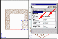
If you've added all the spaces and you need to adjust one or more of them, open the Properties dialog box; then while stretching a space with its grips, watch the Area readout until the area is of the space is what you require. (see Figure 3).


Figure 3: Adjusting Spaces via the Properties dialog box and grips.
(click image to enlarge)

9. Check your walkways to see if they are wide enough. And create another space style called Walkways.

10. Select the Modify Spaces icon from the Spaces toolbar.

11. Select all the offices, the closet, and the kitchen, and press the Enter key to bring up the Modify Space dialog box.

12. At the Modify Space dialog box, change the Space Height to 8'-0", and press OK.

13. Repeat Steps 10-12, selecting the Reception and Conference room, and make their heights 9'-0" and 11'-0" respectively.

14. Select the Convert to Boundaries icon from the Space Boundaries toolbar.

15. Enter SP (for space) in the command line, and press Enter.

16. Select all the spaces, and press Enter to complete the command.

You have now placed space boundaries around all your spaces.

17. Select the Modify Boundary icon from the Space Boundaries toolbar.

18. Select all the space boundaries created in Steps 15 and 16 with a window selection, and press Enter to bring up the Modify Space Boundary dialog box.

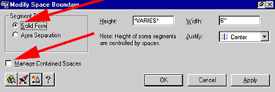
19. At the Modify Space Boundary dialog box, select the Solid Form radio button, and uncheck the Manage Contained Spaces check box (see Figure 4).


Figure 4: Modifying Space Boundaries.

20. Select the Properties icon next to the Question Mark icon at the bottom left of the Modify Space Boundary dialog box to bring up the Space Boundaries Properties dialog box.

21. In this dialog box, select the Design Rules tab.

22. Un-check the Automatically Determine from Spaces check box in that tab.

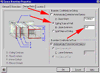
23. Select the Ceiling Stops at Wall radio button, and set the Upper Extension to 2'-0", and then press the OK button (see Figure 5). Press the Apply button and close the dialog boxes.

The Space boundaries are now 2'-0" above the ceiling heights of the spaces.


Figure 5: Setting Space Boundary Properties.
(click image to enlarge)


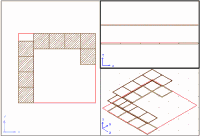
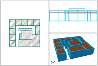
Figure 6: Your basic Space Plan.
(click image to enlarge)

Conclusion
You have now created your basic Space Plan. At this point your plan is still conceptual, and as in all space planning, the spaces will vary somewhat from the program. The beauty of Autodesk Architectural Desktop 3 is that you can now easily modify and refine your plan using your grips and dialog boxes.

In the next article, we will adjust and refine this plan, and quickly convert it into a construction document.


H. Edward Goldberg, AIA, is a practicing architect and industrial designer, as well as Coordinator of Industrial Design at Towson University in Towson, Maryland. Ed can be reached at h.e.goldberg@verizon.net.