Door,
Windows, and Openings
by: Ed Goldberg
URL: http://localhost/gotoPointA.jsp?dest=2_10gold
|
What would a building be without doors and windows? Not only do these objects provide access, light, and ventilation, but they also act as design elements in the building composition. In Autodesk® Architectural Desktop Release 3 and 3.3, the Doors, Windows, and Openings objects are totally parametrically controlled and easy to modify. And they are directly related to the software's intelligent Wall Objects. Once placed in a wall, these objects can quickly be moved or modified while maintaining their relationship to the wall. Try the following tutorial to experience using these intelligent AEC objects.
Creating
the Wall
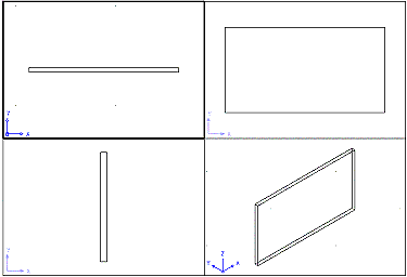
2. Change to the Work_3D layout tab; activate the top-left viewport (Top View). 3. Right-click to bring up the contextual menu and select Design > Walls > Add Wall, which opens the Add Walls dialog box. 4. At the Add Walls dialog box, add a 15' long, 8' high Standard Style wall. Zoom in all viewports (see Figure 1).
Placing
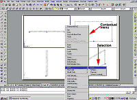
a Door 2. Select Insert > Door to bring up the Add Doors dialog box (see Figure 2).
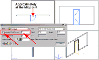
3. At the Add Doors dialog box, check the Automatic Offset/Center check box, and set the dimension in the dimension box opposite it to 4", and then click on the wall approximatly at its midpoint (see Figure 3).
Setting the Automatic Offset/Center check box causes the door, window, or opening to automatically insert at the midpoint of a wall when you click near the middle of the object. In this exercise, we were even more specific and inserted a 4" offset from either end of the wall. No Object Snaps are necessary, and the offset is important because you must maintain a fixed distance from wall intersections to allow for trim and doorknobs. As you know, exterior doors and doors to rooms such as bathrooms need thresholds, which act as barriers that prevent liquids from entering from the outside of the building, or in the case of bathrooms, to prevent water from exiting the room to the hall. Most interior doors except bathroom doors don't usually have thresholds. Displaying
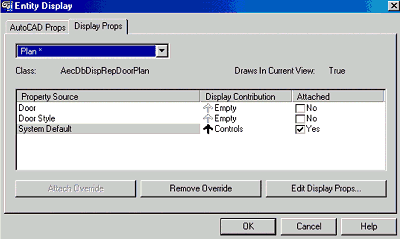
a Door Threshold and Entity Display 2. Select Entity Display to bring up the Entity Display dialog box (see Figure 4), and then click the Display Props tab.
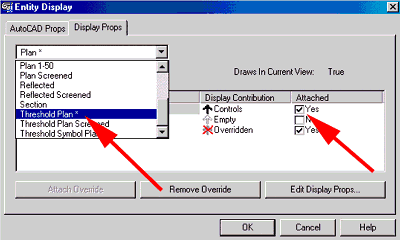
3. Select the check box opposite Door, which attaches an override or modification to this door only from the System Default. From the drop-down list, select Threshold Plan* (see Figure 5).
4. Press the Edit Display Props button to bring up the Entity Properties dialog box. |
|
5. At this dialog box, select the Other tab. Here you will find the threshold controls. 6. Set all the Threshold Dimensions for 2" (see Figure 6).
7. Now select the Layer/Color/Linetype tab, where you will see that the two lightbulbs under the Visible heading are grayed out. (By default, the threshold display is turned off.) 8. To activate that display, select the lightbulb next to Threshold A and Threshold B (the lightbulbs turn yellow indicating they are in the "on" state.) (See Figure 7.) 9. Click the OK button to close the dialog box.
Thresholds A and B now display in the Threshold Plan View and indicate the front and back lines of the threshold (see Figure 8).
Conclusion
|
H. Edward Goldberg, AIA, is a practicing architect and industrial designer, as well as Coordinator of Industrial Design at Towson University in Towson, Maryland. Ed can be reached at h.e.goldberg@verizon.net.
