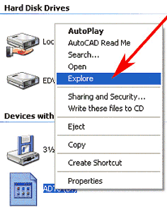
Figure 1: Use Explore to look at the contents of the Autodesk Architectural Desktop 3 CD.
The Detailer
Last month I shared some interesting Autodesk® Architectural Desktop Release 3.0/3.3 productivity hints with everyone. This month and next month I want to talk about Architectural Desktop's Detailer tool.
The Detailer
If you are new to Autodesk Architectural Desktop 3.0/3.3, you probably haven't
heard of the Detailer. This set of routines has been included with Autodesk
Architectural Desktop since Release 1, but is seldom mentioned. The Detailer
does exactly what the name implies: it aids in the creation of 2D details. Take
the following steps to install the program if it is not already installed:

Figure 1: Use Explore to look at the contents of the Autodesk Architectural
Desktop 3 CD.
Installing the Detailer
Program
1. Double-click on the Details folder to show its contents (see Figure 2).
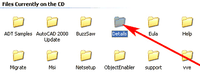
Figure 2: Double-click the Details folder to see its contents.
2. Double-click the setup.exe icon to install the program (see Figure 3).

Figure 3: Double-click setup.exe to install the Detailer.
Starting the Detailer
The main menu should now include the Details drop-down list. As you can see in Figure 4, the Detailer consists of four modules: the Detail Manager, Compose Details, Detail Utilities, and Annotation.
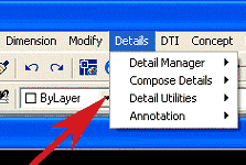
Figure 4: The Detailer has four modules.
Using the Detailer
|
Note: The
Detailer does not take advantage of Autodesk Architectural Desktop's
multiple document capability.
|
The Detailer modules provide the following capabilities:
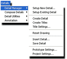
Figure 5: The Details Manager fly-out menu.
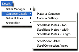
Figure 6: The Compose Details fly-out menu.
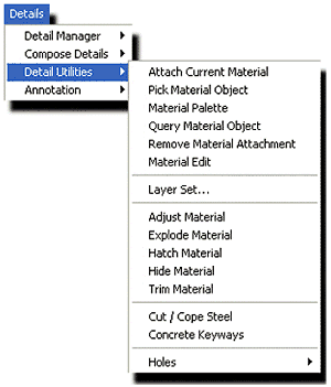
Figure 7: The Detail Utilities fly-out menu.
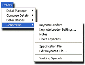
Figure 8: The Annotation fly-out menu.
The Detail Manager...
Hands On
1. Start Autodesk Architectural Desktop 3.0/3.3
2. Select File > New from the main menu, and create a new drawing using the AEC arch [imperial-intl].dwt template.
3. Right-click in any viewport and select Options from the drop-down contextual menu that displays to bring up the Options dialog box.
4. Select the Profiles tab.
5. Select AEC Detail, click the Set Current button, and then click OK to close the dialog box.
6. Select the Model layout tab.
7. Select Details > Detail Manager > Setup New Detail from the main menu to bring up the Drawing Scale and Units dialog box.
8. Select the 1 ½" = 1'-0" drawing scale, and click OK (see Figure 9).
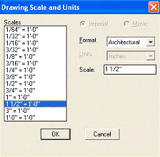
Figure 9: Use the Detailer's Drawing Scale and Units dialog box to set the
scale of your detail.
9. Draw the detail shown in Figure 10, or download the file from here (107 KB).
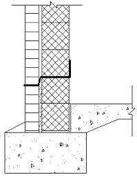
Figure 10: Download file for use in this tutorial. Create your own if you
wish.
10. Select Details > Detail Manager > Create Detail from the main menu.
11. The command line should read "[Detail Creation in progress] Insertion base point."
12. Select the lower-left corner of the detail you have drawn.
13. Select the entire detail with a crossing window.
The command line should tell you that the original drawing factors have been restored. This is fine since you had only set the scale for your detail, and the Detailer was resetting your drawing editor back to the scale of your drawing.
14. Accept the default <Yes> when the command line asks "Save Detail to library?" to bring up the Save Detail dialog box.
15. Fill in the boxes as shown in Figure 11, and then click OK to close this dialog box.
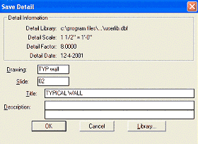
Figure 11: Save your detail with its title and description in a library.
16. Type N at the command line when asked if you wish to "Insert Detail<:Yes>?"
For the purpose of demonstration, close the drawing, and start a new drawing. Be sure to select the AEC Detail Profile.
1. Start Autodesk Architectural Desktop 3.0/3.3
2. Select File > New from the main menu, and create a new drawing using the AEC arch [imperial-intl].dwt template.
3. Right-click in any viewport and select Options from the drop-down contextual menu that displays to bring up the Options dialog box.
4. Select the Profiles tab.
5. Select AEC Details, click the Set Current button, and then click OK to close the dialog box.
6. Select the Work-FLR Layout tab.
7. Change to Paperspace.
8. Select Details > Detail Manager > Insert Detail from the main menu to bring up the Library File dialog box.
9. Select Typ Wall from the Drawing list, and click OK (see Figure 12).
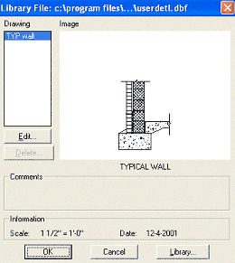
Figure 12: Insert your detail using the Detailer's Insert Detail command.
10. Accept the default at the command line <Block>, and press the Enter key.
11. Place the detail by clicking on a location in your drawing.
12. Press the Enter key to accept the default <0> Rotation angle.
13. Accept the default <Yes> to the command-line question "Add detail title?" by again pressing the Enter key.
14. At "Detail identification:" enter 1, and press the Enter key.
15. At "Detail reference:" enter A3, and press the Enter key.
16. At "Drawing Sheet:" enter A3, and press the Enter key.
17. Select a point at the lower left of your detail, and then select a point at the upper right of your detail to complete the command (see Figures 13and 14).
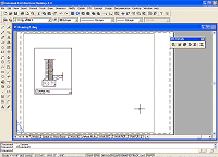
Figure 13: The detail is inserted in PaperSpace.
(click image to enlarge)
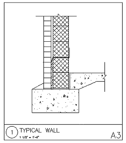
Figure 14: The detail is automatically inserted with title, scale, and
reference numbers.
You have now inserted and labeled your first custom detail from your library. Using the Detailer, you can create, customize, and store dozens of details for use in your Autodesk Architectural Desktop 3.0/3.3 drawings.
The
Detailer: Part 2
by: Ed Goldberg
URL: http://pointa.autodesk.com/gotoPointA.jsp?dest=3_02gold
Last month we looked at the Detail Manager in the Detailer tool included with Autodesk® Architectural Desktop 3.0/3.3. This month I want to discuss the Detailer's Compose Details menu.
|
Note: if you
do not know how to install and activate the Detailer, please read last
month's article for those instructions.
|
Compose Details
The Compose Details menu contains catalogs and routines that speed up the
process of creating the 2D working details that form the core of all
architectural documents. In this tutorial, we'll look at how you can construct
the individual parts of a structure using this menu.
Activating the Detailer
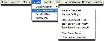
Figure 1: You can now reach the Compose Details menu from the Details menu on
the main toolbar.
Setting Up
The Floor Slab
1. Select Details > Compose Details > Material Compose to open the
Material Retrieval dialog box (see Figure 2).
Figure 2: The building materials listed in the Material Retrieval dialog box are separated into
16 divisions
corresponding to the CSI (Construction Specifications Institute) standards.
(click image to enlarge)
2. In this dialog box select 03—Concrete from the Division list to bring up the Concrete Catalog.
3. At the Concrete Material Catalogs dialog box, double-click on Cast-In-Place to bring up the Material Tables dialog box.
4. At this dialog box double-click on Two-Way Floor joist System to bring up the Two-Way Floor joist System dialog box.
5. At this dialog box select 19"x19"x8" and then press the OK buttons to close all the open dialog boxes.
6. Accept the default material in the Command line, and press the spacebar.
7. Accept Length, and press the spacebar.
8. Accept 3" for slab thickness, and press the spacebar.
9. Select a start point, drag the cursor to the right with Polar on, and enter 8' for the End point.
10. Enter C for center void point, and press the spacebar.
11. Accept the default <Yes> for Hatch joist, and press the spacebar.
12. Enter N for Show reinforcing, and press the spacebar.
You have now created the floor slab (see Figure 3).

Figure 3: The floor slab.
The Masonry Wall
1. At the Material Retrieval dialog box select 04—Masonry from the Division
list to bring up the Masonry Catalog.
2. Press the Catalog button to bring up the Masonry Material Catalogues dialog box (see Figure 4).
3. At this dialog box double-click on Concrete Masonry to bring up the Material Tables dialog box (see Figure 5).
4. Double-click on Fluted Split Block (4 Flutes) to bring up the Fluted Split Block (4 Flutes) dialog box (see Figure 6).
5. Select 12"x8"x16" FLUTED CMU.
6. Press the OK buttons to close all the open dialog boxes until you end up at the Block Specifications dialog box (see Figure 7).
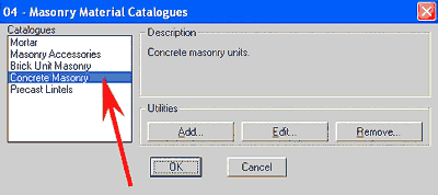
Figure 4. The Masonry Material Catalogues dialog box.
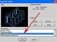
Figure 5: The Material Tables dialog box.
(click image to enlarge)
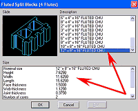
Figure 6: The Fluted Split Blocks dialog box.
(click image to enlarge)
7. At this dialog box select the Section radio button and all the other buttons, checkboxes,
and drop-down list items that are highlighted in Figure 7, and press the OK button.
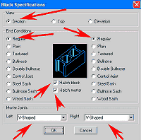
Figure 7: The Block Specifications dialog box.
(click image to enlarge)
8. You will now be back in the drawing editor. With the Intersection Object snap set; insert the block at the top-left corner of the slab you made earlier.
9. Accept Type "S" Mortar at the Command line, and press the spacebar.
10. Press the spacebar again to not create a new base point.
11. Press the spacebar to accept <Courses>.
12. Enter 16 for the number of courses and press the spacebar.
You have now created the masonry (CMU) wall (see Figure 8).
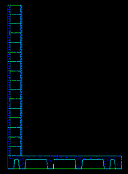
Figure 8: The masonry (CMU) wall.
The Base Plate
1. Select Details > Compose Details > Steel Base Plates—Width from the
main toolbar.
2. In the Command line enter 6", and press the spacebar.
3. Accept 1'-4" for the plate length, and press the spacebar.
4. Enter 3/4" for Plate thickness, and press the spacebar.
5. Enter 5/8" for the Hole diameter, and press the spacebar.
6. Enter 1 for the Number of holes visible in edge, and press the spacebar.
7. Select any location near the top of the masonry wall, accept <0.00> for Rotation angle, and press the spacebar.
8. With the Intersection Object snap <on>, press the spacebar again (don't copy) and select the lower-right corner of the base plate for the New base point.
9. Enter M for move, and press the spacebar.
10. Attach the base plate to the top-right corner of the masonry wall (see Figure 9).
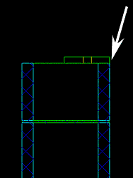
Figure 9: Attaching the base plate.
The Bar Joists
1. At the Material Retrieval dialog box select 05—Metals from the Division
list to bring up the Metals Catalog.
2. Press the Catalog button to bring up the Metals Material Catalogs dialog box.
3. At this dialog box double-click on Joists to bring up the Material Tables dialog box.
4. At this dialog box double-click on H-Series Open Web Joists to bring up the H-Series Open Web Joists dialog box.
5. At this dialog box select 16H4 STEEL JOIST, and then press the OK buttons to close all the open dialog boxes.
6. Enter E for elevation in the command line and press the spacebar.
7. With the Intersection Object snap <on>, snap to the top-right corner of the base plate.
8. Drag your cursor in the direction of <0.00>, enter 7' in the Command line, and press the spacebar.
9. Accept the Bearing length of 2-1/2" and press the spacebar.
You now have completed the bar joist (see Figure 10).
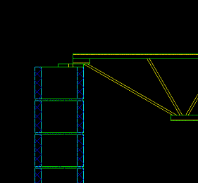
Figure 10: The bar joist.
The Steel Deck and
Rigid Insulation and Metal Decking and Rigid Insulation
1. At the Material Retrieval dialog box select 05—Metals from the Division
list to bring up the Metals Catalog.
2. Press the Catalog button to bring up the Metals Material Catalogs dialog box.
3. At this dialog box double-click on Joists to bring up the Material Tables dialog box.
4. At this dialog box double-click on Roof Decking to bring up the Roof Decking dialog box.
5. At this dialog box select 3DR16 and then press the OK buttons to close all the open dialog boxes.
6. Enter E for End in the command line and press the spacebar.
7. With the OTRACK and
Intersection Object snap
8. At the Material Retrieval dialog box select 07—Thermal Protection from the Division list to bring up the Thermal Protection Catalog.
9. Press the Catalog button to bring up the Thermal Protection Material Catalogs dialog box.
10. At this dialog box double-click on Insulation to bring up the Material Tables dialog box.
11. At this dialog box double-click on Rigid Insulation to bring up the Rigid Insulation dialog box.
12. At this dialog box select 2" RIGID INSULATION and then press the OK buttons to close all the open dialog boxes.
13. With the OTRACK and Intersection Object snap <on>, snap to the left corner of the roof decking and the top of the roof decking (see Figure 11). Drag your cursor in the direction of <0.00> to the right end of the roof decking and click the mouse. Move your cursor in the direction of <90.00> for the Offset side, click the mouse, and press the Esc key to complete the command.
You have now completed the metal decking and rigid insulation details (see Figure 12).
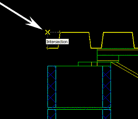
Figure 11: Snapping to the left corner intersection of the roof decking with
Polar, and intersection snap.
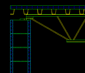
Figure 12: The metal decking and rigid insulation.
Finish detailing this structure by selecting a 5/8" J-bolt fastener and wood ledgers from sections 00 and 06 of the
Material Retrieval dialog box. Do not forget to fill the top core of the CMU wall solid to hold the anchor bolt. See Figure 13 for the completed structure.
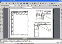
Figure 13: Completed wall section using the Detailer.
(click image to enlarge)
With a little practice, you will find that the Detailer greatly increases productivity. Combine it with Architectural Desktop 3.0/3.3 and
details libraries available on the Internet, and you've got an excellent toolset for creating architectural construction documents.
Have fun.